Now that we have cleared up the fundamental requirements to thrust big-fat rockets into the sky. We are now ready to take a step forward and focus on some minute details in the “Not Rocket Science” way!
Spoiler Alert! The answer to the elephant-ant wordplay is in this article.
Throwback.
Before we start, here is a quick overview.
To overcome the pull of the gravity, we need to push something harder. We figured, throwing things towards earth will do the job, but burning things up will make it easier. As burning (or combustion?) makes the gases hot and fast.
With the example of LPG at home we learned that to burn things we need fuel, oxidizer, and ignition energy. Now what remains is, how do we take care of the combustion in a rocket engine.
Rocket Engine.
At the core, a rocket engine is nothing but a cavity with two sections, Engine Chamber and Nozzle (See Figure 1).
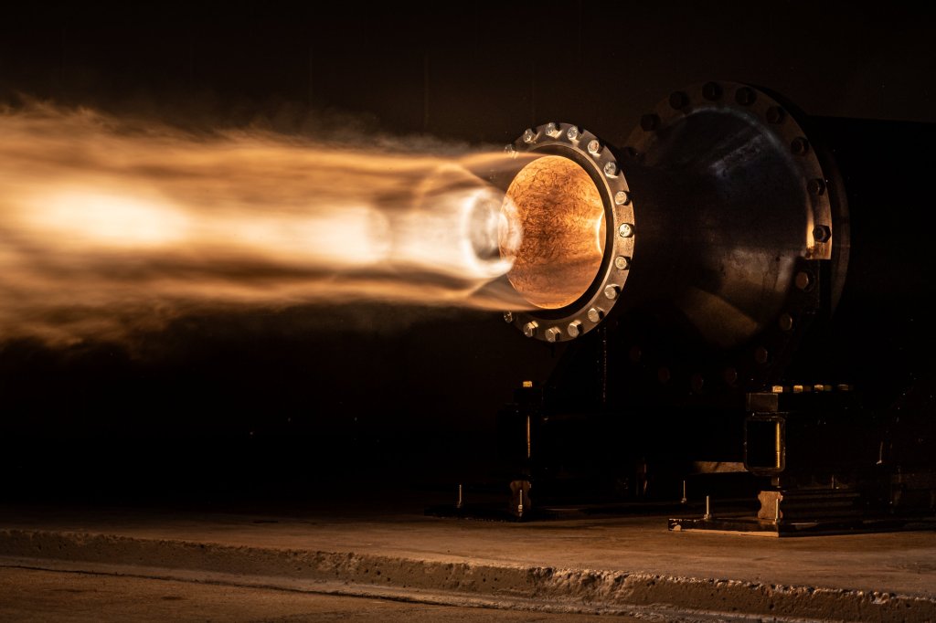
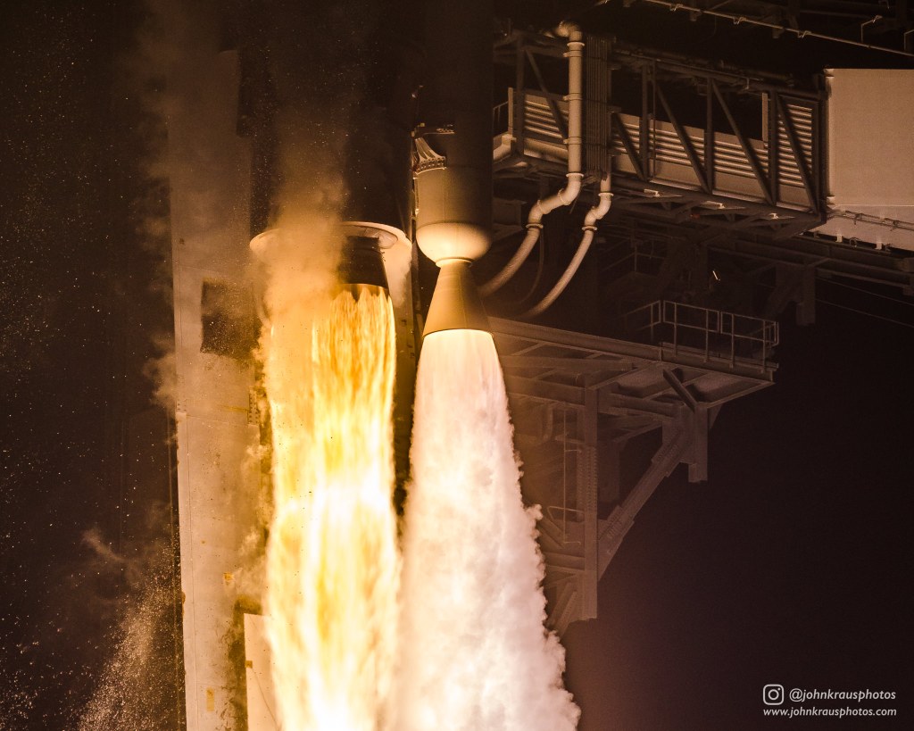
Chamber is that part of the engine where fuel and oxidizer are mixed and ignited. The combustion products are then forced to gush through the nozzle of the engine, which by the way is “the thing” which we see in all the amazing images breathing fire out (See Figure 2).
There is one more feature, actually, the most important design feature in the engine, the throat. What is a throat and how does it work, let’s not worry about that. For now, let’s assume that throat is smallest area in the engine which along with nozzle makes these already hot and fast gases, even faster!
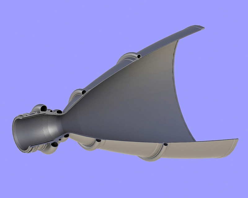
Source: GrabCAD1
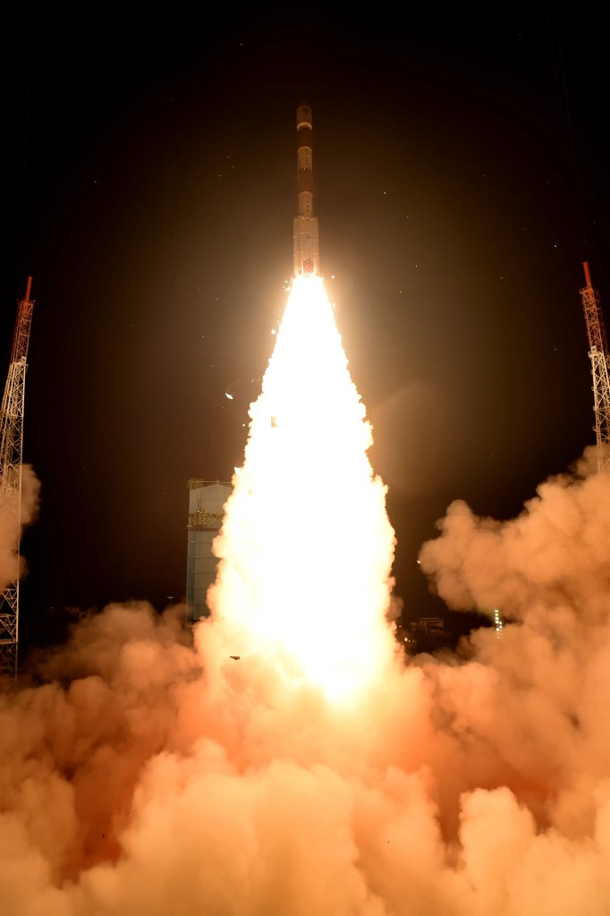
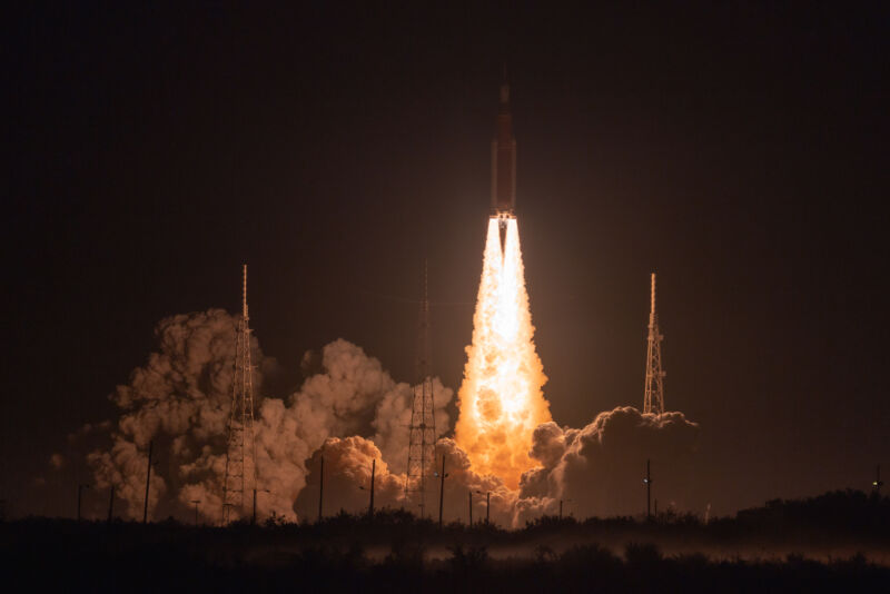
The following are the fire-breathing images of rocket launches across time.

Rocket Chamber.
The part of the rocket engine where the combustion of the oxidizer and the fuel takes place is called the combustion chamber of the rocket or Rocket Chamber. In a liquid rocket, the chamber is empty with at least three inlet points: one for the oxidizer feed line, another for the fuel feed, and lastly the sparkplug for the ignition system.
The configuration of these inlet is designed such that the fuel and the oxidizer mix well with each other. The spark from the sparkplug should be capable to ignite the charge (i.e. mixture of oxidizer and fuel). One of the byproducts of incomplete combustion is soot (i.e. black colored particles) which, if not taken care correctly, sticks to the spark plug terminals and makes it inoperable.
The formation of the soot particles, the temperature of the byproduct gases, and the pressure developed inside the chamber depends on a lot of factors. But among them, the rate at which the oxidizer and fuel are fed into the chamber to combust with each other play an important role. We call it mass flow rate of propellants. And the ratio of the mass flow rate of oxidizer to fuel is called the Oxidizer-to-Fuel Ratio by mass or O/F Ratio. The combustion behavior of the propellant is dependent on the O/F Ratio whereas the thrust generated by the rocket engine is governed by the actual flow rates of the propellants.
Propellant Mass Flow Rate.
There are multiple ways to control the mass flow rate of the propellant being fed to the chamber for combustion. But a lot of constraints are present while designing a compact, reliable, easy to manufacture, and cost effectiveness method of such a requirement. Selecting a dedicated motor for each propellant with its own control logic board is not feasible for CubeSat mission designs.
An inexpensive method of controlling mass flow rate is by drilling small holes in thin metal plates and obstructing the main feed line of the propellant. The small hole is called an “orifice”. It the easiest method to deliver constant mass flow rate in a rocket engine. The delivery of the propellant becomes independent of the environmental conditions, which is a must for reliable firings. Apart from this, orifices assure the safety of the propulsion unit by restricting the propagation of the flame into the propellant storage tank.
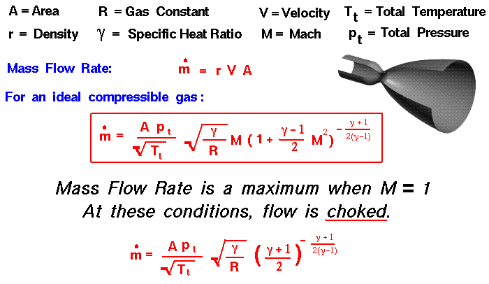
Source: NASA’s Glenn Research Center2
The above formula is for the mass flow rate through any obstructed flow, in the above case a nozzle, but it is reasonably applicable for the orifice as well. If we strip away the other complexities, one can observe that the mass flow rate is directly proportional to the area of the orifice and thus to the square of the size of the orifice. This means that, if the size of the orifice is doubled, the mass flow rate of the propellant become four times the original value (assuming the choking is maintained, and the combustion behavior is not altered)
The importance of the orifice size on the overall performance of the engine and the KPIs is notable, but a comprehensive analysis needs to be performed to understand how slightest change in the orifice dimension affects the thrust from the engine.
Estimation of orifice size.
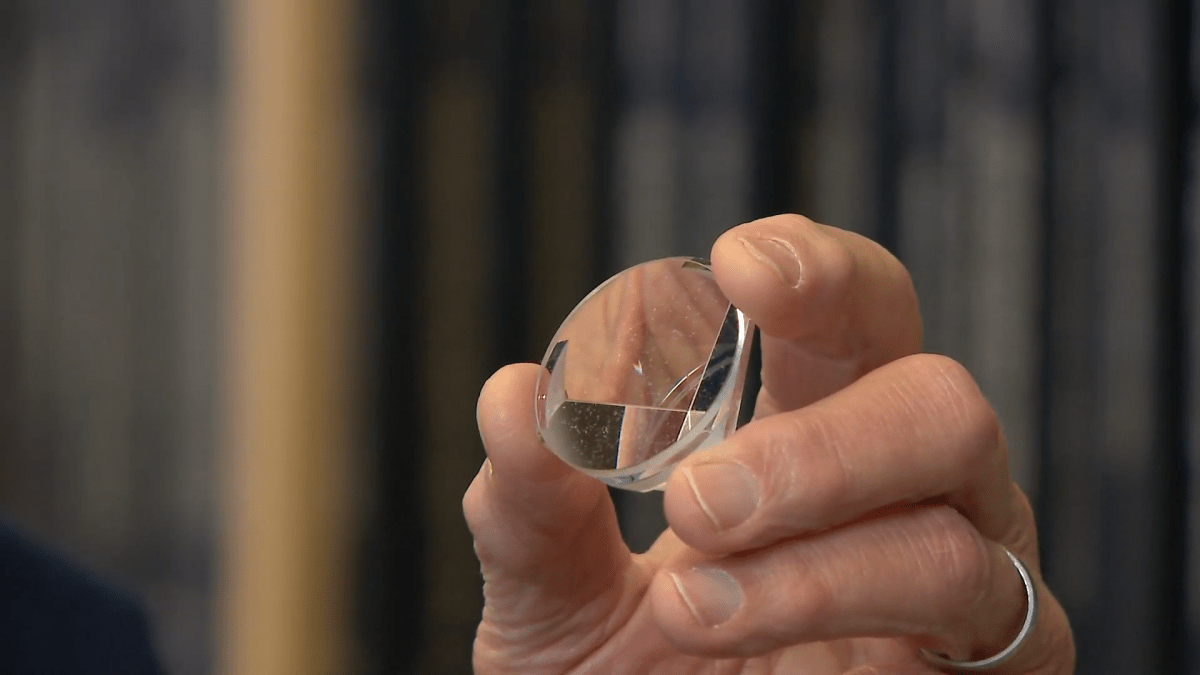
The entire narrative shall now point towards the importance of the size of the orifice for controlling the mass flow rate of fuel and oxidizer in the combustion chamber. Once, we all agree to this, our next step is to measure and diagnose the size of the orifice which is not even visible to human eye in standard conditions. And that is exactly what we are going to unfold next!
References.
- Smoliar, Max. “Rocket Nozzle for Liquid Rocket Engine.” GrabCAD,
Accessed 29 July 2024. ↩︎ - NASA. “Mass Flow Choking.” NASA Glenn Research Center,
Accessed 29 July 2024. ↩︎
TL;DR.
Generated using AI.
- Introduction: Overview of overcoming gravity and the importance of combustion for rocket thrust.
- Rocket Engine Structure: Rocket engine consists of a chamber and a nozzle, with the throat being the critical design feature.
- Rocket Chamber: The combustion chamber mixes and ignites fuel and oxidizer, with design considerations for effective mixing and ignition.
- Propellant Mass Flow Rate: Mass flow rate control via orifices is crucial for reliable and consistent propellant delivery.
- Orifice Size Estimation: Accurate measurement and diagnosis of orifice size are vital for engine performance and thrust optimization.


Leave a comment